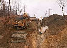
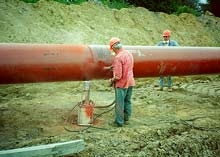
Title Introduction in Materials Science and Engineering

MATERIALS SCIENCE AND ENGINEERING

Materials science involves investigating the relationships that exist between the structures and properties of materials.
Materials engineering is, the basis of these structure–property correlations, designing or engineering the structure of a material to produce a predetermined set of properties. 

So what Structure and property means?

The Definitions of Structure

Structure, the structure of a material usually relates to the arrangement of its internal components.
Subatomic structure involves electrons within the individual atoms and interactions with their nuclei.
On an atomic level, structure encompasses the organization of atoms or molecules relative to one another.
The next larger structural realm, which contains large groups of atoms that are normally agglomerated together, is termed ‘‘microscopic’’
Finally, structural elements that may be viewed with the naked eye are termed ‘‘macroscopic.’’

The Definitions of property

Definitions of properties are made independent of material shape and size. Property  is  a  material  trait  in  terms  of  the  kind  and magnitude  of  response  to  a  specific  imposed  stimulus.
All important properties of solid materials may be grouped into six different categories: mechanical, electrical, thermal, magnetic, optical, and deteriorative.
 Mechanical properties relate deformation to an applied load or force; examples include elastic modulus and strength.
  • Electrical properties, such  as  electrical  conductivity  and  dielectric  constant,  the  stimulus  is  an  electric field.
  •  The thermal behavior of solids can be represented in terms of heat capacity and thermal conductivity.
  • Magnetic properties, demonstrate the response of a material to the application of a magnetic field.
  • Optical properties, the stimulus are electromagnetic or light radiation; index of refraction and reflectivity are representative optical properties.
  • Finally, deteriorative characteristics indicate the chemical reactivity of materials
  In addition to structure and properties, two other important components are involved in the science and engineering of materials, viz. ‘‘processing’’ and ‘‘performance"
The structure of a material will depend on how it is processed. And material’s performance will be a function of its properties. So the interrelationship between processing, structure, properties, and performance is linear.

Processing >>>>>> Structure >>>>>>> Properties >>>>>>> Performance
WHY STUDY MATERIALS SCIENCE AND ENGINEERING?


Before we study this question we should answer, why do we study materials?

Many an applied scientist or engineer, whether mechanical,  civil,  chemical,  or  electrical,  will  at  one  time  or  another  be  exposed  to  a design problem involving materials, materials  scientists  and  engineers  are  specialists  who  are  totally involved in the investigation and design of materials.

So the material selection of many thousand of materials may be a critical problem in which reaching to the final decision. First of all the in-service conditions must be characterized in order to dedicate the required properties of the material, in rare situations the material have the maximum combination of properties so we must trade off one characteristic for another, the classic example is the strength and ductility, whenever high strength material posses limited ductility and vise versa .secondly the expected failure during the operation of the material e.g. significant reductions in mechanical strength may result from exposure to elevated temperatures or corrosive environments. Finally, probably the overriding consideration is that of economics: What will the finished product cost?
READ MORE - Title Introduction in Materials Science and Engineering

Cathodic protection of pipeline

7. Cathodic protection of pipeline

Discovery of the cathodic protection principle

About 1820 the Navy Board was anxious to find the reason why copper sometimes got fouled, whilst iron was dissolving, and at other times the copper was dissolving rather too quickly. A Committee was formed with the Royal Society, of which Sir Humphry Davy was President. Davy had already in 1806 advanced the hypothesis that chemical and electrical charges may be identical, and later convinced Berzelius of this idea. Now, assisted by Michael Faraday, he began to experiment with copper and other metals, such as iron and zinc in various saline solutions, and found the electrochemical reactions he had expected.
In January 1824 Sir Humphry Davy put forward his findings that iron or copper, and for that matter any other metal in saltwater where oxygen is present, forms a galvanic battery and one metal or the other is gradually dissolved, depending on the scale of nobility in the galvanic series. He advocated a small quantity of zinc, or of even cheaper malleable iron, should be placed in contact with copper, and thereby prevent its corrosion. The following year he was able to move away from the laboratory tests and continue his research aboard a naval vessel. Davy found that small "protectors" of malleable iron preserved the copper by the iron gradually dissolving in a galvanic process.

DEFINITIONS :

• Cathodic Protection : Reduction of corrosion rate by shifting the corrosion potential of the electrode toward a less oxidizing potential by applying an external electromotive force.
• Galvanic Anode : A metal which, because of its relative position in the galvanic series, provides sacrificial protection to metals that are more noble in the series, when coupled in an electrolyte.
• Galvanic Cathodic Protection System : A cathodic protection system in which the external electromotive force is supplied by a galvanic anode.
• Impressed Current Cathodic Protection System : A cathodic protection system in which the external electromotive force is provided by an external DC power source.
• Groundbed : One or more anodes installed below the earth's surface for the purpose of supplying cathodic protection.
• Rectifier : A device which converts alternating current to direct current.
• Conventional Groundbed : A group of anodes installed remote (300 feet or more) from the structure and spaced on 15 to 30 foot centers.
• Distributed Anode Groundbed : A group of anodes installed close (5 to 20 feet) to and along a structure to be protected and spaced on 25 to 500 foot centers.
• Deep Anode Groundbed : One or more anodes installed vertically at a nominal depth of 50 feet or more below the earth's surface in a drilled hole.
• Shallow Vertical Groundbed : One or more anodes installed vertically at a nominal depth of 50 feet or less below the earth's surface .


7.1 CATHODIC PROTECTION

Cathodic protection is the most widely applied electrochemical corrosion control technique. This is accomplished by applying a direct current to the structure which causes the structure potential to change from the corrosion potential (Ecorr) to a protective potential in the immunity region.
The required cathodic protection current is supplied by sacrificial anode materials or by an impressed current system. Most metals in contact with an aqueous environment having a near neutral pH can be cathodically protected.

7.2 Applications :
1. Petroleum & Petrochemical:
underground piping and storage tanks, above ground storage tank bottoms, internal surfaces of water storage tanks, heat exchangers and storage well casings

2. Marine:
ships, barges, buoys, steel or reinforced concrete dock structures, offshore pipelines, offshore drilling and production platforms


3. Pulp & Paper:
effluent clarifiers, underground piping, aboveground storage tanks bottoms, foundation pilings, watermains and effluent discharge piping


4. Reinforced concrete structures:
bridges, parking garages and foundations


5. Municipal:
foundation pilings, iron and steel watermains, concrete pressure pipes, sewage treatment clarifiers, sewage pump stations


6. Electrical Power Industry:
cooling water pipelines & intakes, grounding systems, tower footings, penstocks, condensers.


7.3 Type of cathodic protection

7.3.1 GALVANIC CATHODIC PROTECTION SYSTEM

Galvanic anodes are most efficiently used on electrically isolated coated structures. The current output of a galvanic anode installation is typically much less than that which is obtained from an impressed current cathodic protection system.
Galvanic anode installations tend to be used mostly on underground structures in applications where cathodic protection current requirements are small and where earth resistances are acceptably low. as shown in fig(7-1) .

7.3.1.1 Materials :

*Magnesium anodes are available in a variety of shapes and sizes, bare or prepackaged with the most popular being the 17 lb. prepackaged anode. As a general guideline, one may assume magnesium anodes to be acceptable where soil resistivities are between 1,000 ohm-cm and 5,000 ohm-cm. Short chunky shapes are suitable for low resistivity areas, but long slender shapes should be employed in Higher resistivity areas.

*Zinc anodes are also available in many shapes and sizes. They are appropriate in soils with very low resistivities (750 ohm-cm to 1500 ohm-cm). Favorable environments are sea water and salt marshes. Short chunky shapes are suitable for low resistivity areas, but long slender shapes should be employed in higher resistivity areas.

*Aluminum anodes are not commonly used in earth burial applications. Some proprietary aluminum alloy anodes work well in a sea water environment see fig (1)


7.3.1.2 Advantages :

  • Self-powered so no external power source is required.
  • Easy field installation.
  • Low maintenance requirement.
  • Less likely to cause stray current interference problems on other structures.
  • When the current requirement is small, a galvanic system is more economical than an impressed current system.


7.3.1.3 Disadvantages :

  • Low driving voltage.
  • Limited to use in low resistivity soils.
  • Low maintenance requirement.
  • Not an economical source of large amounts of CP current.
  • Very Little capacity to control stray current effects on the protected structure.


Fig(7-1) Sacrificial Anode CP System in Seawater

7.3.2 IMPRESSED CURRENT CATHODIC PROTECTION SYSTEM

An impressed current system is used to protect large bare and coated structures and structures in high resistivity electrolytes. Design of an impressed current system must consider the potential for causing coating damage and the possibility of creating stray currents, which adversely affect other structures See fig (7-2) .
An impressed current system consists of the following components:

  • Rectifier (current supply)
  • Counter electrode
  • Reference electrode


7.3.2.1 Advantages:

  • Flexibility
  • Applicable to a variety of applications
  • Current output may be controlled
  • Not constrained by low driving voltage
  • Effective in high resistivity soils

7.3.2.1 Disadvantages :

  • Increased maintenance
  • Higher operating costs
  • May cause interference on other structures

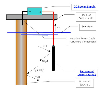
Fig(7-2) Impressed Current Cathodic Protection System


Table (7-1) Comparison of CP System Characteristic

7.4 CATHODIC PROTECTION - THEORY

Carbon steel and stainless steel (depending on the temperature) exposed to seawater will suffer from corrosion. The following reactions will occur on the surface :

• Anodic reaction: Fe → Fe2+ + 2e- eq(7-1)

• Cathodic reactions: O2 + 2H2O + 4e- → 4OH- eq(7-2)

2H+ + 2e- → H2(g) eq(7-3)

These reactions can be shown schematically in a over voltage diagram (E - logi) according to Figure

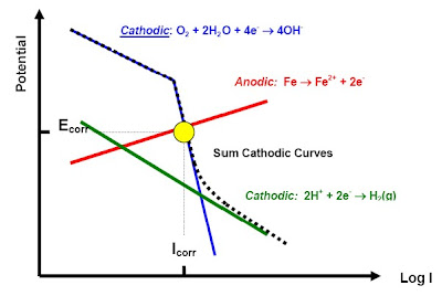
Fig(7-3) Over voltage diagram (E-log I) for steel in seawater

The actual corrosion situation is defined by the crossing of the anodic reaction curve (Eq.7-1) and the sum curve for the cathodic reactions (Eq .(7-2) and (7-3) ).
This corresponds to a corrosion potential of Ecorr and a corrosion current density
icorr ( i = Icorr/Area). The corrosion rate is proportional to the current density icorr.
The corrosion potential Ecorr for carbon steel is in the order of -600 mV vs. Ag/AgCl(1). As can be seen from the Pourbaix diagram this indicate that carbon steel will be in the corrosion region in water with pH = 7. One way to reduce the corrosion rate is to lower the potential into the immune region of the Pourbaix diagram. According to Fig(7-3),
a lowering of the potential will also reduce the current density on the anodic reaction (iron dissolution). This is called cathodic protection (CP) and is achieved by supplying an external current to the structure to be protected.

Fig (7-4) Overvoltage diagram for steel in seawater with protection current IP included

Figure (7-4) shows the E-logI curve with a cathodic current IP added. As can be seen from the figure the lowering of the potential caused by the external current, will reduce the anodic dissolution of iron according to Eq. (7-1) – see the yellow point in the figure.
For carbon steel in seawater the normal corrosion potential Ecorr is in the range -550 to -600 mV vs. Ag/AgCl. To achieve protection a potential EP ≤ -800 mV vs. Ag/AgCl is normally required for carbon steel in seawater .
Cathodic protection from sacrificial anodes is based on the principle of galvanic corrosion. This means that a less noble material is connected to the structure (metal) to be protected. To select the right sacrificial anode material, the galvanic series is important.
From this series one can see that carbon steel normally has a corrosion potential in the range -550 to -600 mV vs. SCE(2) in seawater. To reduce the potential by installing sacrificial anodes, an anode material with a potential more negative that -600 mV vs. SCE needs to be selected. The figure indicates that zinc and aluminum alloys are well suited as sacrificial anodes when protecting carbon steel.
Figure (7-4) also shows how the hydrogen reaction is more and more dominating when the potential is lowered. This is reason why it is important to restrict the min. potential on steels that can suffer from hydrogen induced cracking.
This protection current can be supplied in two different ways, as schematically shown in Figure (7-5) :

  • Impressed current from an external power source
  • Sacrificial anodes


Fig(7-5) A schematic picture of the cathodic protection principle with

a) sacrificial anodes
b) impressed current.

7.5 DESIGN OF A CATHODIC PROTECTION SYSTEM

7.5.1 Steps in a design

7.5.1.1 Preparation of the design basis

Before the design work starts a design basis shall be prepared and accepted by the customer/ management before the work starts. The design basis shall include the following information:

  • Which standard or recommended practice to base the design upon
  • Type of protection; sacrificial anodes or impressed current
  • Combined protection with coating
  • Current densities to be used (if not directly in accordance with the standard)
  • Protection potentials (as above)
  • If coating – type of coating and degradation rate
  • Deviations from actual standard/RP
  • Documentation to base the design upon
  • Is the structure in electrical contact with other structures permanently or from time to time?
  • Documentation level for the design


7.5.1.2 Definition of surface area to be protected

Based on the documentation of the actual structure the total surface to be protected shall be calculated. Assuming that different parts of the structure see different temperature levels and/or different water depths, total areas for the different regions shall be specified. Which region to divide the structure into shall be specified in the “Design Basis”.

Total area AT = Σ A1 + A2 + … An, n = 1 – m eq (7-4)

7.5.1.3 Calculation of total protection current

Total protection current IT shall be calculated from the following equation:
IT = Σ (i1xA1 + i2xA2 + … inxAn) eq (7-5)
Where : i1, …in corresponds to the current density for area A1, … An.

three different current values have to be calculated :

1. Initial current, II: Cathodic current that is required to give an effective polarization of the surface shortly after exposure start up.
II = Σ(iI1xA1 + iI2xA2 + … + iInxAn) eq (7-6)

2. Average current, IA: Average or maintenance current as a measure of the anticipated cathodic current once the cathodic protection system has attained its steady state protection potential.
IA = Σ(iA1xA1 + iA2xA2 + … + iAnxAn) eq (7-7)

3. Final current, IF: Current required at the end of the exposure period with developed calcareous deposits and marine growth. It takes into account the additional current required to re-polarize the steel surface if the calcareous layer is partly and periodically damaged, e.g. by severe storms.
IF = Σ(iF1xA1x + iF2xA2 + … + iFnxAn) eq (7-8)

Assuming that the protection system consists of a combination between coating and cathodic protection, the required current for protection is multiplied with:

*Coating breakdown factor, fb: Anticipated reduction in cathodic current due to the application of an electrically insulating coating.

1. Total initial current:
ITI = Σ(iI1xA1xfbI1 + iI2xA2xfbI2 + … + iIn xA n x fbIn) eq (7-9)

2. Total average current:
ITA = Σ(iA1xA1xfbA1 + iA2xA2xfbA2 +…+ iAn x An x fbAn) eq (7-10)

3. Total final current:
ITF = Σ(iF1xA1xfbF1 + iF2xA2xfbF2 + … + iFnxAnxfbFn) eq (7-11)

* Situation with no coating on the surface:
Required protection current for the actual lifetime
IP = Max (II, IA, IF) eq(7-12)


*Situation with a combination between coating and cathodic protection:
Required protection current for the actual lifetime
IP = Max (ITI, ITA, ITF) eq (7-13)


7.5.1.4 Calculation of total anode weight

Total required anode weight mTA (or mass) based on the average total current ITA is calculated according to the following equation:
mTA = (ITA x t x 8670)/(U x C) eq(7-14)

where:

t = Lifetime (years)
U = Utilization factor for the anode
C = Anode capacity (Ah/year)
8670 = # hours / year


7.5.1.5 Selection of anode type and size
Anode size and shape shall be selected. The most frequent used sacrificial anode types and shapes are shown in Fig(7-6).

Fig(7-6) Anode Shape

a) Stand off,
b) Flush mounted,
c) Bracelet (Jotun Cathodic Protection – today Skarpenord Corrosion)

Anodes should be selected in standard size according to information from an accepted anode supplier. As soon as the actual anode type, material and size is selected anode parameters like:

  • Utilization factor U
  • Anode capacity C
  • Anode resistance Ra

can be defined from the supplier documentation and/or calculations.


Anodes Types :

• Scrap iron is sometimes used as an anode simply because it is available. Non-uniform consumption, high rate of consumption, and discoloration of surrounding structures are distinct disadvantages.

• Graphite anodes are one of the most commonly used anodes for impressed current systems. Most common applications are to protect underground structures. Graphite anodes are suitable for deep, shallow vertical, or horizontal ground beds with carbonaceous backfill.


• High Silicon Cast Iron anodes are widely used in underground applications in both shallow and deep ground beds. Specially formulated high silicon cast iron anodes are also used in seawater.
Although the performance is Improved with coke breez , its use is no critical


• Platinized Titanium anodes take advantage of the low consumption rate and high current density. Voltages in excess of 10 Volts will result in severe pitting of the titanium core causing premature failure.


• Platinized Niobium/Tantalum anodes also take advantage of the properties of platinum, but avoid the low driving voltage restriction of platinized titanium anodes. Breakdown of the niobium oxide film occurs at approximately 120 Volts. Thus these anodes are used where high driving voltage is required.


• Magnetite anodes are quite expensive but have an extremely long life. They are therefore an economical choice for some applications.
.


• Mixed Metal Oxide anodes consist of a high purity titanium substrate with an applied coating consisting of a mixture of oxides. The titanium serves as a support for the oxide coating. The mixed metal oxide is a crystalline, electrically-conductive coating that activates the titanium and enables it to function as an anode. When applied on titanium, the coating has an extremely low consumption rate, measured in terms of milligrams per year. As a result of this low consumption rate, the tubular dimensions remain nearly constant during the design life of the anode - providing a consistently low resistance anode.


7.5.1.6 Anode resistance calculation

The anode resistance Ra shall be calculated according to the formulas given in
Table (7-2).

Table (7-2) Anode resistance formulas


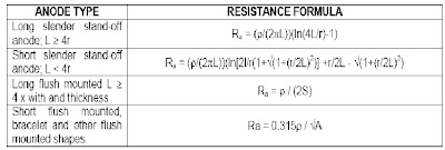
ρ = Seawater resistivity (Ωm)
L = Length of anode (m)
r = Anode radius (m)
S = Arithmetic mean of anode length and with
A = exposed anode surface area (m2)

7.5.1.7 Calculation of number of anodes

Based on the selected anode type with weight ma, the required number of anodes,
NT1 , shall be calculated based on the following equation:
NT = MTA / ma eq(7-15)

7.5.1.8 Calculation of current output from each anode

For the selected anode type, the number of anodes to deliver the total current shall be calculated for initial current ITI and total current ITF.

1. Current output from the anode – initial condition:
IaI = | EP – Ea | / RaI eq(7-16)

2. Current output from the anode – final condition:
IaF = | EP – Ea | / RaF eq(7-17)

Where:

EP = Protection potential (mV vs. Ag/AgCl)
Ea = Anode potential (mV vs. Ag/AgCl)
RaI = Anode résistance for initial anode size (Ωm)
RaF = Anode résistance for final anode size (Ωm)


7.5.1.9 Calculation of number of anodes

Number of anodes NI based on initial conditions:
NI = ITI / IaI eq(7-18)

1. Number of anodes NI based on final conditions:
NF = IFI / IaF eq (3.19)

2. Select the final number N of anodes from:
N = Max (NI, NF, NT) eq(7-20)

7.5.2 Distribution of anodes
Anodes shall be distributed in a way that secure as even current- and potential distribution on the structure as possible. The following general rules can be given:

1. Secure an even distribution of anodes on a symmetrical structure (pipe)
2. Install more anodes close to a region with concentrated surface areas (node point)
3. Always install anodes under sea level

(1) Silver chloride = Ag / AgCl
(2) Saturated Calomel = SCE
READ MORE - Cathodic protection of pipeline

Types of Corrosion

6. Corrosion of pipeline

6.1 TYPES OF CORROSION

Basically, there are four ways corrosion can occur. Corrosion can occur through a chemical reaction or three general types of electrochemical reactions. The three general types of electrochemical reactions that occur depend on the cause of the potential difference between the anode and the cathode. This potential difference can be caused by differences in the environment, differences in the metal, or by external electrical sources of DC current. Understanding this principle leads to an understanding of the principles of operation of cathodic protection systems. Each of these three types of corrosion will be explained in detail, with examples of each. These three types are general corrosion, concentration cell corrosion (electrochemical cell caused by differences in the electrolyte), galvanic corrosion (electrochemical cell caused by differences in the metal), and stray current corrosion (electrochemical cell caused by external electrical sources).

6.1.1 General Corrosion.

This type of corrosion is chemical or electrochemical in nature. However, there are no discrete anode or cathode areas. This form of corrosion is uniform over the surface of the metal exposed to the environment. The metal gradually becomes thinner and eventually fails.
The energy state of the metal is basically what causes this reaction. Referred to as the “dust-to-dust” process, high levels of energy are added to the raw mmaterial to produce the metal. This high energy level causes an unnaturally high electrical potential. One law of chemistry is that all materials will tend to revert to its lowest energy level, or its natural state. After high levels of energy are added to the metal, when it is exposed to the environment (an electrolyte), it will tend to revert to its natural state. This process is normally extremely slow, and is dependent on the ion concentration of the electrolyte that it is exposed to. Only under very extreme conditions (acidic electrolyte) can this form of corrosion be significant. The corrosion rate for steel climbs drastically at a pH below 4, and at a pH of about 3 , the steel will dissolve.
General corrosion tends to slow down over time because the potential gradually becomes lower. Failures of pipelines or tanks would not quickly occur from this type of corrosion since no pitting or penetration of the structure occurs, just a general corrosion over the entire surface (except under very extreme circumstances where the metal could dissolve in an acid electrolyte). However, in nature, the metal is not completely uniform and the electrolyte is not completely homogeneous, resulting in electrochemical corrosion cells that greatly overshadow this mild form of corrosion.

6.1.2 Concentration Cell Corrosion.

This type of corrosion is caused by an electrochemical corrosion cell. The potential difference (electromotive force) is caused by a difference in concentration of some component in the electrolyte. Any difference in the electrolyte contacting the metal forms discrete anode and cathode regions in the metal. Any metal exposed to an electrolyte exhibits a measurable potential or voltage. The same metal has a different electrical potential in different electrolytes, or electrolytes with different concentrations of any component. This potential difference forces the metal to develop anodic and cathodic regions. When there is also an electrolyte and a metallic path, the circuit is complete, current flows, and electrochemical corrosion will occur. Soil is a combination of many different materials. There are also many different types of soil, and even the same type of soil varies greatly in the concentration of its constituents. Therefore, there is no such thing as truly homogeneous soil.
These soil variations cause potential differences (electromotive force) on the metal surface resulting in electrochemical corrosion cells. Liquids tend to be more uniform, but can vary in the concentration of some components such as


Fig (6-1). Concentration Cell Caused by Different Environments

oxygen varies by depth and flow rates. Biological organisms are present in virtually all-natural aqueous environments, these organisms tend to attach to and grow on the surface of structural materials, resulting in the formation of a biological film, or biofilm. These films are different from the surrounding electrolyte and have many adverse effects. Following are examples of common forms of concentration cell corrosion.


6.1.2.1 Dissimilar Environment.

Pipelines tend to pass through many different types of soils. The metal exhibits different electrical potentials in different soils. The electrical potential in those soils determines which areas become anodic and which areas become cathodic. Since both the anode and cathode are electrically continuous and the electrolyte is in contact with both, current flows, resulting in oxidation and reduction reactions (corrosion and protection). The area of the pipeline or tank, which is the anode, corrodes. Since the ground tends to consist of horizontal layers of dissimilar soils, pipelines that traverse several layers of soil tend to be affected by this type of corrosion frequently. Water and oil well casings are prime examples of this type of electrochemical corrosion cell. Other examples are pipelines that go through areas of generally different materials such as rock, gravel, sand, loam, clay, or different combinations of these materials. There are over 50 general types of soil that have been characterized for corrosion properties. Each of the different types of soils has different soil resistivity values. In areas where the soil resistivity values vary greatly in relatively short distances, dissimilar environment corrosion cells are formed. These types of electrochemical corrosion cells are most serious when the anode is relatively small, soil resistivity is the lowest and the electrical potential difference is the greatest. Examples of corrosive soils are Merced (alkali) silt loam, Montezuma (alkali) clay adobe, muck, and Fargo clay loam.

6.1.2.2 Oxygen Concentration.


Pipelines or tanks that are exposed to an electrolyte with a low oxygen concentration are generally anodic to the same material exposed to an electrolyte with a high oxygen content. This is most severe when a pipeline or tank is placed on the bottom of the excavation, then backfill is placed around the remaining part of the structure. The backfill contains a relatively high amount of oxygen during the excavation and backfill operation. This can also occur when the metal is exposed to areas that have different levels of oxygen content.

Fig (6-2) Concentration Cell Caused by Different Concentrations of Oxygen


6.1.2.3 Moist/Dry Electrolyte.

Pipelines or tanks that are exposed to areas of low and high water content in the electrolyte also exhibit different potentials in these different areas. Generally, the area with more water content becomes the anode in this electrochemical corrosion cell. This is most severe when a pipeline passes through a swampy area adjacent to dry areas or a tank is located in dry soil, but the water table in the soil saturates the tank bottom.

Fig( 6-3) Concentration Cell Caused by Different Concentrations of Water

6.1.2.4 Non-Homogeneous Soil.

Pipelines or tanks that are exposed to an electrolyte that is not homogeneous exhibit different electrical potentials in the different components of the soil. This can occur in any soil that is a mixture of materials from microscopic to substantially sized components. The area(s) with the higher potential becomes the anode in this electrochemical corrosion cell. This is most severe when a pipeline or tank is placed in an electrolyte with components that cause large potential differences or where there are small anodic areas and large cathodic areas.

Fig(6-4) Concentration Cell Caused by Non-Homogeneous Soil

6.1.2.5 Concrete / Soil Interface.

Pipelines or tanks that are in contact with cement and exposed to another electrolyte exhibit different potentials in each area. The area not in contact with cement becomes the anode in this electrochemical corrosion cell. A pipeline or tank that is in contact with concrete and soil (or water) may be a very severe corrosion cell, because of the high potential difference of the metal in the two different electrolytes.

Fig(6-5) Concentration Cell Caused by Concrete and Soil Electrolytes


6.1.2.6 Backfill Impurities.

This is similar to the non-homogeneous soil concentration cells, except that the “backfill impurities” are materials that do not normally occur in the soil, but are foreign materials mixed into the electrolyte during or between the excavation and the backfill process. This can be any material that forms anodic or cathodic areas on the structure. It can also be an isolating material that forms different conditions in the electrolyte, or a metallic material which actually becomes an anode or cathode when in contact with the structure (galvanic corrosion).

6.1.2.7 Biological Effects.

Biological organisms may attach to and grow on the surface of a metal, causing a different environment that in some cases may be extremely corrosive to the metal. Most bacteria that have been implicated in corrosion grow best at temperatures of 15 oC to 45 oC (60 oF to 115 oF). These bacteria are generally classed by their oxygen requirements, which vary widely with species, and may be aerobic or anaerobic. Their metabolism products influence the electrochemical reaction by forming materials or films (slime) that act as a diffusion barrier, or change ion concentrations and pH. Some bacteria are capable of being directly involved in the oxidation or reduction of metal ions and can shift the chemical equilibrium that influences the corrosion rate. Aerobic bacteria form oxygen and chemical concentration cells, and in the presence of bacteria capable of oxidizing ferrous ions, further accelerate corrosion. Many produce mineral or organic acids that may also breakdown structure coatings. The breakdown products are then sometimes usable as food, leading to accelerated corrosion.

6.1.3 Galvanic Corrosion.

This type of corrosion is caused by an electrochemical corrosion cell developed by a potential difference in the metal that makes one part of the cell an anode, and the other part of the cell the cathode. Different metals have different potentials in the same electrolyte. This potential difference is the driving force, or the voltage, of the cell. As with any electrochemical corrosion cell, if the electrolyte is continuous from the anode to the cathode and there is a metallic path present for the electron, the circuit is completed and current will flow and electrochemical corrosion will occur.

6.1.3.1 Dissimilar Metals.

The most obvious form of this type of corrosion is when two different kinds of metal are in the electrolyte and metallically bonded or shorted in some manner. All metals exhibit an electrical potential; each metal has its distinctive potential or voltage (paragraph 2-4). When two different metals are connected, the metal with the most negative potential is the anode; the less negative metal is the cathode. An “active” metal is a metal with a high negative potential, which also means it is anodic when compared to most other metals. A “noble” metal is a metal with a low negative potential, which also means it is cathodic when compared to most other metals.
Dissimilar metal corrosion is most severe when the potential difference between the two metals, or “driving voltage,” is the greatest.

Fig(6-6) Galvanic Corrosion Cell Caused by Different Metals

Examples of active metals are new steel, aluminum, stainless steel (in the active state), zinc, and magnesium. Examples of noble metals are corroded steel, stainless steel (in the passivated state), copper, bronze, carbon, gold, and platinum.
One example of this type of corrosion occurs when coated steel pipelines are metallically connected to bare copper grounding systems or other copper pipelines (usually water lines).

6.1.3.2 Old-to-New Syndrome.

This type of corrosion can also be rather severe. Steel is unique among metals because of the high energy put into the process of producing the steel . New steel is more active, than corroded steel.
The potential difference between the high negative potential of the new steel and the low negative potential of the old steel is the driving force, or voltage, of this electrochemical corrosion cell.


Fig(6-7) Galvanic Corrosion Cell Caused by Old and New Steel


A severe and common example of this type of corrosion is when an old bare steel pipeline fails, and a small section of the pipeline is replaced with a coated section of new steel. The new section is the anode and corrodes to protect the large cathode, resulting in failure of the new section.

6.1.3.3 Dissimilar Alloys.

The most obvious example of this type of corrosion is different metal alloys. For example, there are over 200 different alloys of stainless steel.
Also, metals are not 100 percent pure. They normally contain small percentages of other types of metals. Different batches of a metal vary in content of these other metals. Different manufacturers may use different raw materials and even the same manufacturer may use raw materials from different sources. Each batch of metal may be slightly different in electrical potential. Even in the same batch of metal, the concentration of these other materials may vary slightly throughout the finished product. All these differences will produce the electromotive force for this type of corrosion to occur.

6.1.3.4 Impurities in Metal.

No manufacturing process is perfect. Small impurities may be mixed into the metal as it is produced or cooled. Impurities at the surface of the metal may become part of the electrolyte causing concentration cell corrosion, or if metallic, they may be anodic (corrodes and leaves a pit behind), or cathodic (corroding surrounding metal).

6.1.3.5 Marred or Scratched Surface.

A marred or scratched surface becomes anodic to the surrounding metallic surface. This is similar to the old-to-new syndrome, where new steel is anodic to the old steel. This electrochemical corrosion cell is set up by the difference in the electrical potential of the scratched surface compared to the remaining surface of the structure. Threaded pipe, bolts, marks from pipe wrenches and other tools, and marks from shovels and backhoes are common examples of this type of electrochemical corrosion cell. This situation is further aggravated because the metal thickness is also reduced in these areas.


Fig(6-8) Galvanic Corrosion Cell Caused by Marred and Scratched Surfaces

6.1.3.6 Stressed Metallic Section.

Metal that is under stress becomes anodic to metal that is not under stress. Bolts, bends, structural or mechanical stresses, and soil movement are common examples. This situation results in the metal shearing or cracking from the stress long before corrosion has penetrated the entire thickness of the structure.

26.1.3.7 Temperature.

Metal that is at an elevated temperature becomes anodic to the same metal at a lower temperature. As previously discussed, a more active metal is anodic to a more noble metal. Since elevated temperature makes a metal more active, it becomes anodic to the rest of the metal. This electrochemical corrosion cell may cause accelerated corrosion on metals that are at elevated temperatures.

6.1.3.8 Simultaneous Sources of Corrosion.

Each of these previously discussed types of electrochemical corrosion cells may cause significant corrosion, but in many cases there are a combination of many different types of corrosion simultaneously at work to make corrosive situations even worse on the metal surface. Understanding the actual cause of corrosion is of utmost importance in maintaining a submerged or buried metallic structure, such as a pipeline or storage tank.
When corrosion is noted, or when a corrosion leak occurs, it is essential that
the cause of the corrosion be identified so that corrective action can be taken. Once the type of corrosion is understood, the method of repairing the cause of the corrosion can be easily determined and future leaks can be prevented. In many cases, the location of the anodic area can be predicted by understanding the process of corrosion. These anodic areas tend to be in the worst possible places. Examples are pipeline river or swamp crossings, pipelines entering pits or foundations, pipelines under stress and pipelines at elevated temperatures.
In a majority of leak situations, the primary concern is to patch the hole in the pipeline or tank. Without an understanding of corrosion and corrosion control, a bad situation can be made even worse. Even considering the criticality of stopping a gushing leak, it is imperative to fix the cause of the leak. This means taking action to identify and mitigate the cause of the leak. In some situations it may be a failed insulator or broken bond wire which actually caused the leak. Probably the most common cause of corrosion leaks are the methods or materials used from previous leak repairs, breaking or shorting the continuity. An example of many types of corrosion at work simultaneously can be demonstrated by the following figure, which shows most of the different types of corrosion discussed.

Fig(6-9) Combination of Many Different Corrosion Cells at Work

6.1.4 Stray Current Corrosion.

This type of electrochemical corrosion cell is caused by an electromotive force from an external source affecting the structure by developing a potential gradient in the electrolyte or by inducing a current in the metal, which forces part of the structure to become an anode and another part a cathode. This pickup and discharge of current occurs when a metallic structure offers a path of lower resistance for current flowing in the electrolyte. This type of corrosion can be extremely severe because of very high voltages that can be forced into the earth by various sources.
The potential gradient in the electrolyte forces one part of the structure to pick up current (become a cathode) and another part of the structure to discharge current (become an anode).
Stray current corrosion occurs where the current from the external source leaves the metal structure and enters back into the electrolyte, normally near the external power source cathode. The external power source is the driving force, or the voltage, of the cell. Stray current corrosion is different from natural corrosion because it is caused by an externally induced electrical current and is basically independent of such environmental factors as concentration cells, resistivity, pH and galvanic cells. The amount of current (corrosion) depends on the external power source, and the resistance of the path through the metallic structure compared to the resistance of the path between the external source’s anode and cathode.

Fig (6-10) Stray Current Corrosion Cell Caused by External Anode and Cathode

An example of stray current corrosion is caused by impressed current cathodic protection systems, where a “foreign” electrically continuous structure passes near the protected structures anodes and then crosses the protected structure (cathode). This corrosion is usually found after failures in the foreign structure occur. Stray current corrosion is the most severe form of corrosion because the metallic structure is forced to become an anode and the amount of current translates directly into metal loss. If the amount of current leaving a structure to enter the electrolyte can be measured, this can be directly translated into metallic weight loss. Different metals have specific amounts of weight loss when exposed to current discharge. This weight loss is normally measured in pounds (or kilograms) of metal lost due to a current of one amp for a period of one year (one amp-year). For example, if a stray current of just two amps were present on a steel pipeline, the result would be a loss of 18.2 kilo grams (40.2 pounds) of steel in one year. For a coated pipeline, this could result in a penetration at a defect in the coating in an extremely short period of time, sometimes only a few days.

6.1.4.1 DC Transit Systems.


Electrified railroads, subway systems, street railway systems, mining systems, and trolleys that operate on DC are major sources of stray current corrosion. These systems may operate load currents of thousands of amperes at a common operating potential of 600 volts. Tracks are laid at ground level and are not completely insulated from the earth. Some part of the load current may travel through the earth. In the event of a track fault, these currents could be extremely high. Buried or submerged metallic structures in the vicinity (several miles) of these tracks could be subject to stray current effects. Pipelines that run parallel, cross under the tracks, or are located near the DC substation, are especially prone to these stray currents. If there are high resistance joints in the pipeline, the current may bypass the joint, leaving the pipeline on one side of the joint, and returning on the other side. Since the source of the stray current is moving, it may be necessary to monitor the metallic structure over a 24-hour period to see if these currents affect it.
Figure 2-11. Stray Current Corrosion Cell Caused by a DC Transit System

6.1.4.2 High Voltage Direct Current (HVDC) Electric Transmission

Lines. Power distribution systems are another source of stray currents. Most power systems are AC, although sometimes DC systems with grounded neutral may be used. These transmission lines, under fault conditions, may use the earth as the return path for the DC current. Because DC requires only two-wire instead of three-wire transmission, it is sometimes used when large amounts of power needs to be transported large distances.
Conversion units are located at each end of the transmission lines.
Each of these conversion units are connected to a large ground grid. Any unbalanced load would result in a current in the earth between these two ground grids. These unbalanced currents are naturally not constant they vary in direction and magnitude. HVDC line voltages may be 750,000 volts or higher.

Fig(6-12) Stray Current Corrosion Cell Caused by an HVDC Transmission System
READ MORE - Types of Corrosion

Cathodic Protection of Pipeline ( corrosion )

1 - principles of corrosion

  • Introduction
  • 1.1 importance of corrosion studies
  • 1.2 Examples of Catastrophic Corrosion Damage
  • 1.2.1 Sewer explosion, Mexico
  • 1.2.2 Loss of USAF F16 fighter aircraft
  • 1.3 corrosion definition
  • 1.3.1 THE CONSEQUENCES OF CORROSION
  • 1.4 corrosion principles
  • 1.5 classification of corrosion

2. Forms of corrosion

  • 2.1 Uniform corrosion or general corrosion
  • 2.1.1 Mechanisms
  • 2.1.2 Prevention or Remedial Action
  • 2.2 Galvanic
  • 2.2.1 Mechanism
  • 2.2.2 Important factors in galvanic corrosion
  • 2.2.3 Prevention or Remedial Action
  • 2.3 crevice
  • 2.3.1 MECHANISM
  • 2.3.1.2 Stage two of a crevice formation (Restricted Convection)
  • 2.3.1.3 Stage three of a crevice formation(Obstruction and Electromigration)
  • 2.3.2 Prevention
  • 2.4 Pitting
  • 2.4.1 Characteristics of Pitting Corrosion
  • 2.4.2 Mechanisms
  • 2.4.3 Prevention or Remedial Action
  • 2.5 Stress-corrosion cracking (SCC)
  • 2.5.1 Mechanisms
  • 2.5.2 Prevention
  • 2.6 intergranular corrosion
  • 2.6.1 Mechanisms
  • 2.6.2 Prevention
  • 2.7 selective leaching
  • 2.7.1 Mechanisms
  • 2.7.2 Prevention
  • 2.8 Erosion Corrosion
  • 2.8.1 Mechanism
  • 2.8.2 Prevention or Remedial Action

3. Environment Effects

  • 3.1 Atmospheric Corrosion
  • 3.1.1 Types of atmospheres and environments
  • 3.1.2 Important practical variables in atmospheric corrosion
  • 3.1.2.1 Time of wetness
  • 3.1.2.2 Sulfur dioxide
  • 3.1.2.3 Chlorides
  • 3.1.2.4 Nitrogen compounds
  • 3.1.2.5 Temperature
  • 3.2 Corrosion By Water
  • 3.2.1 Effect OF Electrolyte Composition
  • 3.2.1.1 Conductivity
  • 3.2.1.2 Hydrogen Ion Concentration (pH)
  • 3.2.1.3 Dissolved Gases
  • 3.2.1.3.1 Oxygen
  • 3.2.1.3.2 Carbon Dioxide
  • 2.1.3.3 Hydrogen Sulphide
  • 3.2.1.3.4 Chloride Ions
  • 3.2.2 PHYSICAL VARIABLES
  • 3.2.2.1 Temperature
  • 3.2.2.2 Pressure
  • 3.2.2.3 Velocity
  • 3.2.2.4 Erosion/Velocity
  • 3.3 Soil in the Corrosion Process
  • 3.3.1 The Corrosion Process in Soil
  • 3.3.2 Properties of Soils Related to Corrosion
  • 3.3.3 Types of Soil Moisture

4. corrosion protection

  • 4.1 FACTORS THAT CONTROL THE CORROSION RATE
  • 4.2 Material selection
  • 4.2.1 Alloy steels
  • 4.2.2 Stainless steels
  • 4.2.1.2 Low-alloy weathering steels
  • 4.3 Corrosion Prevention
  • 4.3.1 Conditioning the Metal This can be sub-divided into two main groups:

(a) Coating the metal, in order to interpose a corrosion resistant coating between metal and environment. The coating may consist of:

Coating type

  • 1. Internal Lining
  • 2. Fusion Bonded Epoxy (FBE) Powder Coating
  • 3. Dual Fusion Bonded Epoxy (D-FBE ) coating
  • 4. Bitumen / Asphalt Enameln (AE) Coating
  • 5. Three Layer Polypropylene (3LPP) Coating
  • 6. Three Layer Polyethylene (3LPE) Coating
  • 7. Concrete Weight Coating (CWC)
  • 8. Polyurethane Insulation Coating
  • 9. Polypropylene Insulation Coating

(b) Alloying the metal

  • 4.3.2 Conditioning the Corrosive Environment
  • 4.3.3 Electrochemical Control

5. preparation of pipeline

  • 5.1 Stringing
  • 5.2 Trenching
  • 5.3 Pipe Bending
  • 5.4 Welding
  • 5.5 Coating
  • 5.6 Lowering In
  • 5.7 Backfilling
  • 5.8 Hydrostatic Test
  • 5.9 Restoration
  • 5.10 Open Cut River and Stream Crossings
  • 5.11 Directional Drilling
  • 5.12 Wetlands
  • 5.13 road Bores
READ MORE - Cathodic Protection of Pipeline ( corrosion )

preparation of pipeline

preparation of pipeline


5.1.1 Stringing
At steel rolling mills where the pipe is fabricated, pipeline representatives will carefully inspect new pipe to assure that it meets industry and federal government safety standards. For corrosion control, the outside surface will be treated with a protective coating.
The pipe will be transported from the pipe mill to a pipe storage yard in the vicinity of the pipeline location. The pipe lengths typically are 40 to 80 feet long. A stringing crew using specialized trailers will move the pipe from the storage yard to the pipeline right-of-way. The crew will be careful to distribute the various pipe joints according to the design plan since the type of coating and wall thickness can vary based on soil conditions and location.


Fig(5-1) Stringing Process

For example, concrete coating may be used under streams and wetlands, and heavier wall pipe is required at road crossings and in special construction areas.


5.1.2 Trenching
The trenching crew will use a wheel trencher or backhoe to dig the pipe trench. The U.S. Department of Transportation (DOT) requires the top of the pipe to be buried a minimum of 30 inches below the ground surface in rural areas, so the depth of the trench will be at least five to six feet deep for pipe 30 to 36 inches in diameter. For less rural areas, the pipe must be buried a minimum of 36 inches. The pipe will be buried even deeper at stream and road crossings.


Fig (5-2) Trenching Process

If the crew finds large quantities of solid rock during the trenching operation, it will use special equipment or explosives to remove the rock. The contractor will use explosives carefully, in accordance with state and federal guidelines, to ensure a safe and controlled blast.

In cultivated areas the topsoil over the trench will be removed first and kept separate from the excavated subsoil, a process called top soiling. As backfilling operations begin, the soil will be returned to the trench in reverse order with the subsoil put back first, followed by the topsoil. This process ensures the topsoil is returned to its original position.

5.1.3Pipe Bending

The pipe bending crew will use a bending machine to make slight bends in the pipe to account for changes in the pipeline route and to conform to the topography.
The bending machine uses a series of clamps and hydraulic pressure to make a very smooth, controlled bend in the pipe. All bending is performed in strict accordance with federally prescribed standards to ensure integrity of the bend.


Fig (5-3) pipe bending Process

5.1.4 Welding

The pipe gang and a welding crew will be responsible for welding, the process that joins the various sections of pipe together into one continuous length. The pipe gang uses special pipeline equipment called side booms to pick up each joint of pipe, align it with the previous joint and make the first part (pass) of the weld. The pipe gang then moves down the line to the next section repeating the process. The welding crew follows the pipe gang to complete each weld.
In recent years, contractors have used semi-automatic welding units to move down a pipeline and complete the welding process. Semi-automatic welding, done to strict specifications, still requires qualified welders, and personnel are required to set up the equipment and hand-weld at connection points and crossings.
As part of the quality-assurance process, each welder must pass qualification tests to work on a particular pipeline job, and each weld procedure must be approved for use on that job in accordance with federally adopted welding standards. Welder qualification takes place before the project begins. Each welder must complete several welds using the same type of pipe as that to be used in the project. The welds are then evaluated by placing the welded material in a machine and measuring the force required to pull the weld apart. It is interesting to note that the weld has a greater tensile strength than the pipe itself.

A second quality-assurance test ensures the quality of the ongoing welding operation. To do this, qualified technicians take X-rays of the pipe welds to ensure the completed welds meet federally prescribed quality standards. The X-ray technician processes the film in a small, portable darkroom at the site. If the technician detects any flaws, the weld is repaired or cut out, and a new weld is made. Another form of weld quality inspection employs ultrasonic technology.

5.1.5 Coating

Line pipe is externally coated to inhibit corrosion by preventing moisture from coming into direct contact with the steel.
Normally, this is done at the mill where the pipe is manufactured or at another coating facility location before it is delivered to the construction site.
All coated pipe, however, has uncoated areas three to six inches from each end to prevent the coating from interfering with the welding process. Once the welds are made, a coating crew coats the field joint, the area around the weld, before the pipeline is lowered into the ditch.


Fig (5-4) Coating Process

Pipeline companies use several different types of coatings for field joints, the most common being fusion bond epoxy or polyethylene heat-shrink sleeves. Prior to application, the coating crew thoroughly cleans the bare pipe with a power wire brush or sandblast to remove any dirt, mill scale or debris. The crew then applies the coating and allows it to dry prior to lowering the pipe in the ditch. Before the pipe is lowered into the trench, the coating of the entire pipeline is inspected to ensure it is free of any defects.
5.1.6 Lowering In

Lowering the welded pipe into the trench demands close coordination and skilled operators. Using a series of side-booms, which are tracked construction equipment with a boom on the side, operators simultaneously lift the pipe and carefully lower the welded sections into the trench. Non-metallic slings protect the pipe and coating as it is lifted and moved into position.
In rocky areas the contractor may place sandbags or foam blocks at the bottom of the trench prior to lowering-in to protect the pipe and coating from damage.


Fig (5-5) Lowering In Process

5.1.7 Backfilling

Once the pipe has been placed in the trench, the trench can be backfilled. This is accomplished with either a backhoe or padding machine depending on the soil makeup. As with previous construction crews, the backfilling crew takes care to protect the pipe and coating as the soil is returned to the trench. As the operations begin, the soil is returned to the trench in reverse order, with the subsoil put back first, followed by the topsoil.
This ensures the topsoil is returned to its original position. In areas where the ground is rocky and coarse, crews screen the backfill material to remove rocks, or bring in clean fill to cover the pipe or the pipe is covered with a material to protect it from sharp rocks. Once the pipe is sufficiently covered, the coarser soil and rock can be used to complete the backfill.

Fig (5-6) Backfilling Process

5.1.8 Hydrostatic Test

Before the pipeline is put into natural gas service, the entire length of the pipeline is pressure tested using water. The hydrostatic test is the final construction quality assurance test. Requirements for this test are also prescribed in DOT’s federal regulations. Depending on the varying elevation of the terrain along the pipeline and the location of available water sources, the pipeline may be divided into sections to facilitate the test.
Each section is filled with water and pressured up to a level higher than the maximum operating pressure. The test pressure is held for a specific period of time to determine if it meets the design strength requirements and if any leaks are present. Once a test section successfully passes the hydrostatic test, water is emptied from the pipeline in accordance with state and federal requirements. The pipeline is then dried to assure it has no water in it before gas is put into the pipeline.

5.1.9 Restoration

The final step in the construction process is restoring the land as closely as possible to its original condition. Depending on the project’s requirements, this process typically involves decompacting the construction work areas, replacing topsoil, removing large rocks that may have been brought to the surface, completing any final repairs to irrigation systems or drain tiles, applying lime or fertilizer, restoring fences, etc.

The restoration crew carefully grades the right-of-way and in hilly areas, installs erosion-prevention measures such as interceptor dikes, which are small earthen mounds constructed across the right-of-way to divert water


Fig (5-7) restoration Process

The restoration crew also installs riprap, consisting of stones or timbers, along streams and wetlands to stabilize soils.
As a final measure the crew may plant seed and mulches the construction right-of-way to restore it to its original condition

• SPECIAL CONSTRUCTION TECHNIQUES

5.1.10 Open Cut River and Stream Crossings

This crossing method involves excavating a trench across the bottom of the river or stream to be crossed with the pipeline. Depending on the depth of the water, the construction equipment may have to be placed on barges or other floating platforms to excavate the pipe trench. If the water is shallow enough, the contractor can divert the water flow with dams and flume pipe to allow backhoes, working from the banks or the streambed, to dig the trench.
The contractor prepares the pipe for the crossing by stringing it out on one side of the stream or river and then welding, coating and hydrostatically testing the entire pipe segment. Sidebooms carry the pipe segment into the stream bed, similar to construction on land, or the construction crew floats the pipe into the river with flotation devices and positions it for burial in the trench. Concrete weights or concrete coating ensure the pipe will stay in position at the bottom of the trench once the contractor removes the flotation devices.

5.1.11 Directional Drilling

Another crossing method is the use of directional drilling. While not always feasible, this method avoids the excavation of a trench across the bottom of the crossing. It is a method considered for longer crossings and requires special geological conditions at the crossing location. Basically, it involves drilling a hole large enough for the pipeline to be pulled through it and in the shape established by the designers.

Fig (5-8) Directional Drilling Process

5.1.12 Wetlands

"Pipelining" in wetlands or marshes requires another special construction technique. In one technique, crews place large timber mats ahead of the construction equipment to provide a stable working platform. The timber mats act much like snowshoes, spreading the weight of the construction equipment over a broad area. The mats make it possible to operate the heavy equipment on the unstable soils.

5.1.13 Road Bores


For crossing most small roads pipeline contractors use the "open-cut" method. Traffic is diverted while the contractor digs the trench across the road and installs the pipeline. The contractor subsequently repairs the road bed and replaces the pavement.
For highways and major roads with heavy traffic, pipeline contractors often use road bores to install the pipeline. Similar to a directional drill for river crossings, the road bore is accomplished with a horizontal drill rig, or boring machine. The boring machine drills a hole under the road to allow insertion of the pipe. In some instances a casing is first installed in the hole, and the gas pipeline is inserted inside the casing. The benefit of the road bore is that it allows installation of the pipeline without disrupting traffic.

READ MORE - preparation of pipeline


Followers